2 How the hardware components work and are configured
2.1 How PWM is used to dim LEDs
2.2 How the PWM frequency is configured
2.3 How the duty-cycle is configured
2.4 Designing the PWM configuration
2.4.1 Trade-offs in choosing the PSC-value and ARR-value
2.4.2 Determining the PSC-value and ARR-value for dimmable LEDs
Chapter 13, part 1:
Using PWM to Implement Dimmable LEDs
12/20/21
1 Introduction
This article describes how pulse width modulation (PWM) can be used to implement dimmable LEDs on an STM32 dev-board. The first part of the article presents concepts related to how the hardware components work and are configured. The second part describes code that implements the dimmable LEDs.
This article is an introductory tutorial for those who are new to timers and PWM signals. A timer is used to generate the PWM signal. STM32 timers are complex, and their documentation is hard to use. As a beginner, the tutorials I found were hard to understand, had errors, or they did not have all of the info needed. This article presents my understanding of how dimmable LEDs are implemented, based on several documents and tutorials, which are cited.
This article is part of a study-guide for the book Hands-On RTOS with Microcontrollers. This article supplements Chapter 13, as the chapter doesn't describe its PWM implementation, nor the related example programs. For the book, the dev-board used is an STM32 Nucleo-144, NUCLEO-F767ZI. The article should be applicable to other STM32 MCUs.
2 How the hardware components work and are configured
2.1 How PWM is used to dim LEDs
An LED is made dimmable by using PWM to power the LED's positive lead. This article assumes an elementary understanding of PWM and duty cycles. That info can be found in the articles listed below. (For the Wikipedia articles, the introductory sections are sufficient.)
● Frequency: https://blogs.arubanetworks.com/industries/frequency-cycle-wavelength-amplitude-and-phase/
● PWM: https://en.wikipedia.org/wiki/Pulse-width_modulation
● Duty cycle: https://en.wikipedia.org/wiki/Duty_cycle
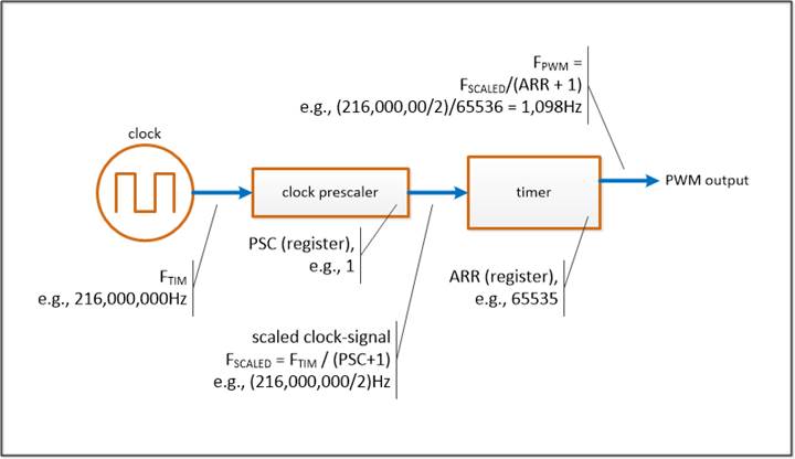
On the dev-board, PWM is generated by these hardware components: a clock, clock prescaler, and timer. They are illustrated below, and descriptions follow.
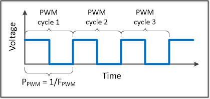
The PWM signal is illustrated below.
FPWM : the PWM frequency; the number of PWM cycles per second
PPWM : the PWM period; (1/ FPWM)
With PWM, the duty-cycle is the part of the PWM-cycle in which the signal is high, as illustrated below. Configuring a timer to generate PWM output includes specifying the PWM frequency (FPWM) and the duty-cycle. For dimmable LEDs, the PWM frequency should be at least 100Hz, to avoid visible flicker [STM08, pg5]. An STM tutorial on dimmable LEDs uses an FPWM of 1KHz, so that frequency will be used here [STMa, pg33].
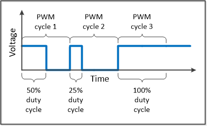
The LED brightness is proportional to the duty-cycle value. With a duty-cycle of 0% the LED is off. At 100% the LED is at its brightest. If the ratio between duty-cycle and brightness is linear, then a 50% duty-cycle, would make the LED half as bright as 100%. (I don't know what the actual ratio is.)
2.2 How the PWM frequency is configured
The PWM signal is generated by a clock, clock prescaler, and timer. This section describes how they are configured to generate a particular PWM frequency. An earlier figure shows the components, and how they are configured.
STM32 supports many different types of PWM. The type presented here appears to be commonly used for dimming an LED, and it's used in the Chapter 13 example-programs. In particular, the type presented here is: PWM mode 1, in edge-aligned mode, with up-counting. Those PWM attributes are not explained here. However, to use the cited STM references, it can be necessary to know the PWM type being used.
The terminology used here is adapted from an STM tutorial [STMa, pgs31-33]. Among the tutorials I found, it was the easiest to understand. However, its equations on duty-cycle and PWM-resolution are incorrect, as described in the bibliography, below.
As shown in the figure, the timer's input is a scaled
clock-signal, with frequency FSCALED. The scaled
clock-signal is generated by using a system clock and a clock prescaler.
The system clock's frequency is referred to as FTIM (timer
operating frequency). The clock-prescaler is used to reduce the FTIM.
The clock-prescaler is embedded in the timer. Its PSC register is used
to set FSCALED:
FSCALED tics/sec = [FTIM tics/sec] / (PSC + 1)
The PSC register is set by the user, and it can be 0 to 65,535 [STMa, pg 6]. (PSC + 1) is the scaling value. Adding one allows scaling values to potentially be 1 to 65,536.
The scaled clock-signal's period (PSCALED) is:
PSCALED sec/tic = 1 / (FSCALED tics/sec)
The dev-board used here is a NUCLEO-F767ZI. It's maximum CPU frequency is 216MHz, and the timers can be run at that rate, or slower [STM21a, pages 1, 18]. In the earlier figure, the example values shown are:
FTIM =
216MHz
PSC = 1
FSCALED = 216MHz / (1 + 1) = 108MHz
The timer has an auto-reload register (ARR), which is used in setting the PWM frequency. The ARR register is set by the user, and it can be 0 to 65,535.
(ARR + 1) is the auto-reload value. It specifies the number of scaled-clock ticks in a PWM cycle.
The timer outputs a PWM signal. The PWM frequency is the number of PWM cycles in a second:
FPWM cycles/sec = [FSCALED tics/sec] / [(ARR + 1) tics/cycle]
In calculating FPWM, the "tic" units are from the scaled clock-signal.
The PWM period (PPWM) is the length of the PWM cycle, in seconds:
PPWM sec/cycle = [1 / (FSCALED tics/sec)] * [(ARR + 1) tics/cycle]
2.3 How the duty-cycle is configured
The duty-cycle is specified by setting the register CCRx [STM18, page 985f]. For a PWM cycle, the number of scaled-clock tics that the signal is active (high) is the value in CCRx. The value can be 0 to 65,535.
For particular CCRx and ARR values, the duty_cycle is:
duty_cycle = CCRx / (ARR + 1)
A CCRx value of 0 results in a duty-cycle of 0%. A CCRx value greater than ARR results in a duty-cycle of 100%. If ARR is 65,535, a duty-cycle of 100% is not possible. In that case, the PWM cycle is 65,536 scaled-clock tics, but CCRx can be at most 65,535. So, when ARR is 65,535, the maximum duty-cycle is (65,535/65,536).
The CCRx value can be calculated as shown below, for particular duty-cycle and ARR values. Rounding is to the nearest integer. The minimum function accommodates the cases where rounding is to 65,536, as with an ARR of 65,535 and a duty-cycle of 100%.
CCRx = minimum( round(duty_cycle * (ARR + 1)), 65535)
As a cautionary note, an STM tutorial that's cited here has incorrect equations for the PWM duty-cycle [STMa]. This was described earlier.
2.4 Designing the PWM configuration
2.4.1 Trade-offs in choosing the PSC-value and ARR-value
For a given system-clock frequency, the PWM output is configured by choosing the PSC-value and ARR-value. For each, the possible values are 1 to 65,536. Increasing the PSC-value decreases FPWM. Increasing the ARR-value also decreases FPWM. Another consideration for the ARR-value is that the larger it is, the more accurate the duty-cycle implementation can be, for a given PWM period (PPWM).
For example, if the ARR-value is 3, there are 3 scaled-clock ticks per PWM cycle. The duty-cycles that can be implemented are: 0 (0 ticks), 1/3 (1 tick), 2/3 (2 ticks), or 1 (3 ticks). If a duty-cycle of 1/2 is needed, the closest possible duty-cycles are 1/3 (1 tick) or 2/3 (2 ticks). Regardless of which is chosen, the implemented duty-cycle will be 1/6 off from what is needed, e.g., (1/2 - 1/3 = 1/6).
In general, the implemented duty-cycle will be off from what
is needed by up to 1/(ARR_value*2).
So, for a given PWM period (PPWM), the larger the ARR is, the more
accurate the duty-cycle implementation can be.
For the PSC-value, the smaller it is, the more accurate the duty-cycle calculation can be, for a given PWM period (PPWM).
The optimum amounts for the PSC-value and ARR-value depend upon the objectives for the PWM output. Also, for a system with multiple variables, like this, it's often not possible to create an algorithm for calculating optimal results.
2.4.2 Determining the PSC-value and ARR-value for dimmable LEDs
For dimmable LEDs, it appears that a PWM frequency (FPWM) of 1,000Hz works well. One way to implement that PWM frequency is to use the largest ARR-value. Two techniques for finding that value will be described.
The first technique uses the maximum ARR-value (65,536). The PSC-value is varied, and FPWM is calculated. The results are shown below. A PSC-value of 3 results in an FPWM of 1098.6Hz, which is close enough to the objective of 1,000Hz.
|
|
|
|
(calculated) |
|
FTIM |
PSC_value |
ARR_value |
FPWM |
|
216000000 |
1 |
65536 |
3295.9 |
|
216000000 |
2 |
65536 |
1647.9 |
|
216000000 |
3 |
65536 |
1098.6 |
|
216000000 |
4 |
65536 |
824.0 |
|
216000000 |
5 |
65536 |
659.2 |
In the second technique, the PSC-value is varied, and the ARR-value is calculated [STMa, page 31]. The equation for the ARR-value is derived from the equations for FPWM and FSCALED:
ARR = ( FTIM / (FPWM * (PSC + 1) ) - 1
A PSC-value of 3 cannot be used as it requires an ARR-value
of 71,999, and the maximum ARR-value is 65,536. A PSC-value of 4 can be used,
and it requires an ARR-value of 53,999. However, the earlier solution is
preferable, with a PSC-value of 3 and an ARR-value of 65,536. By using a lower
PSC value and higher ARR value, the duty-cycle calculation is more precise.
|
|
|
|
(calculated) |
|
FTIM |
PSC_value |
FPWM |
ARR_value |
|
216000000 |
1 |
1000 |
215999 |
|
216000000 |
2 |
1000 |
107999 |
|
216000000 |
3 |
1000 |
71999 |
|
216000000 |
4 |
1000 |
53999 |
|
216000000 |
5 |
1000 |
43199 |
3 How the dimmable LEDs are implemented
The book has an implementation of dimmable LEDs, in the Chapter 13 example programs. This section describes how the PWM frequency and the duty-cycle are configured. Speculative explanations are stated using terms such as, "appears to be...", or "apparently...".
The relevant code is in pwmImplementation.c. There, the function PWMInit() configures the needed hardware: clocks, timers, GPIOs, and LEDs. The brightness of the board's LEDs is set by the functions SetBlueDuty(), SetRedDuty(), and SetGreenDuty().
The book's example programs are on GitHub. pwmImplementation.c is here:
The code for PWMInit() is probably generated by STM32CubeIDE. STM has a tutorial on how to use that IDE to generate code for a dimmable LED [STM20].
STM32 supports many different types of PWM output. The PWM type implemented in pwmImplementation.c appears to be: PWM mode 1, in edge-aligned mode, with up-counting. An STM tutorial lists the specific settings needed for that PWM mode [STM21b, page 16].
This line specifies PWM mode 1:
sConfig.OCMode = TIM_OCMODE_PWM1;
This line specifies up-counting:
TimHandle.Init.CounterMode = TIM_COUNTERMODE_UP;
I couldn't find a way to select edge-aligned mode directly. It appears to get selected by specifying up-counting [STM21b, page 16].
These lines set the PSC and ARR registers:
uint32_t uhPrescalerValue = (uint32_t)((SystemCoreClock/2) / 21600000) - 1;
TimHandle.Init.Prescaler = uhPrescalerValue;
TimHandle.Init.Period = 65535;
How those lines set the PSC and ARR registers:
● SystemCoreClock is a global system variable. When this code runs it will have the system clock frequency, which is 216,000,000. This was confirmed by running the code.
● uhPrescalerValue gets assigned the value 4.
● TimHandle.Init.Prescaler gets assigned to the PSC register, apparently
● TimHandle.Init.Period gets assigned to the ARR register, apparently
So, the ARR register will be 65,535, and thus the PWM cycle will be 65,536 scaled-clock tics.
The PSC register will be 4, so the scaling-value will be 5.
With those PSC and ARR register values, the PWM frequency will be:
FPWM cycles/sec = [FSCALED tics/sec] / [(ARR + 1) tics/cycle]
FPWM = 659.2 cycles/sec
For the blue LED, the duty-cycle is set by this line:
TIM4->CCR2 = DutyCycle/100.0 * 65535;
● DutyCycle is a float, and it specifies a percentage, between 0 and 100.0, e.g., 50.0
● TIM4->CCR2 is a CCRx register. It is set to an integer value between 0 and 65,535.
As described earlier, if ARR is 65,535, a 100% duty-cycle isn't possible. When the DutyCycle is 100.0, CCR2 gets set to 65,535, and the actual duty-cycle will be 65,535/65,536.
4 Bibliography
4.1 Cited sources
These sources are cited in the article. The most useful were: [STM21b], [STM18], and [STMa].
[STM08] STM, "LED dimming implemented on STM32 microcontroller", Application note AN2841, November 2008
● Basic LED dimming is described on page 5
[STM18] STM, "Reference manual : STM32F76xxx and STM32F77xxx advanced Arm-based 32-bit MCUs", RM0410, March 2018
● Section 26.3.9 "PWM mode", pages 985f
o Shows details of how CCRx works, which implements the duty-cycle.
[STM20] STM, "Timer lab: PWM generation using HAL library", part of the course "STM32CubeIDE Basics", 2020
● Shows how to use STM32CubeIDE to generate code for a dimmable LED.
● A video, and slides
o Video: https://www.youtube.com/watch?v=-AFCcfzK9xc
o Video description has a link to the slides.
● The video is part of the STM course "STM32CubeIDE Basics":
o https://www.youtube.com/playlist?list=PLnMKNibPkDnFCosVVv98U5dCulE6T3Iy8
[STM21a] STM, "STM32F767xx ... Datasheet", DS11532 Rev 7, February 2021
● Clock and timers specified on pages 1 and 18
[STM21b] STM, "STM32 cross-series timer overview", Application note AN4013, June 2021
● Section 2.5 "Timer in PWM mode", page 15f
o Describes how to configure the timer for PWM mode.
o In the phrase, "To configure the timer in this mode:", the term "this mode" has an ambiguous antecedent (page 16). "This mode" refers to PWM-mode as a whole, not to just PWM mode 2.
[STMa] STM, "STM32L4 - Timers : Advanced-control, general-purpose, and basic timers", Revision 2.0, undated.
● Errors:
o The equations for duty-cycle and PWM-resolution are incorrect.
o I posted an error-description here:
● Presentation slides:
o https://www.st.com/resource/en/product_training/STM32L4_WDG_TIMERS_GPTIM.pdf
● Relevant sections:
o Counting period management, page 6
o PWM calculations, pages 31-33
o Dimmable LEDs, pages 31-33
4.2 Other sources
● STM, "General-purpose timer cookbook for STM32 microcontrollers", Application note AN4776, July 2019
o Notes: advanced topics
● vuquangtrong, "Timers and their modes"
o https://www.codeinsideout.com/blog/stm32/timer/
o Notes:
■ A tutorial for STM32 timers. Includes a dimmable LED.
■ I haven't read it, but it might be good.
(c) Jim Yuill 2021, with MIT License